Model:

Require:
– Configure so that the PC can ping 8.8.8.8 (loopback of R10 in the picture)
– Core switches have VRRP redundancy
– Fortigate firewall configuration active and backup clusters
Note: FORTIGATE EVE 6.4 should be used here, There is a problem with version 7.X
Configuration on R10 ISP: (On ISP switch, leave defaults)
Configuration on LAN switch 3:
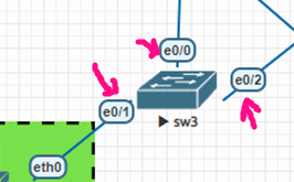
VLAN100,200
Interface Ethernet 0/1
Switch port access VLAN 100
Switch port mode access
Interface Ethernet 0/0
Switch port trunking allows VLAN 100,200
Switch port trunk encapsulation dot1q
switch port mode trunking
Interface Ethernet 0/2
Switch port trunking allows VLAN 100,200
Switch port trunk encapsulation dot1q
switch port mode trunking
Configuration on LAN switch 4:
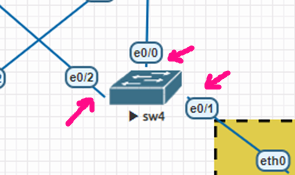
VLAN 100,200
Interface Ethernet 0/1
Switch port access VLAN 200
Switch port mode access
Interface Ethernet 0/0
Switch port trunking allows VLAN 100,200
Switch port trunk encapsulation dot1q
switch port mode trunking
Interface Ethernet 0/2
Switch port trunking allows VLAN 100,200
Switch port trunk encapsulation dot1q
switch port mode trunking
Configuration on core_sw01:
VLAN 100,200,300
Interface Ethernet 0/0
Switch port trunking allows VLAN 100,200
Switch port trunk encapsulation dot1q
switch port mode trunking
!
Interface Ethernet 0/1
Switch port trunking allows VLAN 100,200
Switch port trunk encapsulation dot1q
switch port mode trunking
!
Interface Ethernet 0/2## Message sent to firewall
Switch port access VLAN 300
Switch port mode access
!
Interface Ethernet 0/3## Message sent to firewall
Switch port access VLAN 300
Switch port mode access
!
Interface Ethernet 1/0##Port to PC_MGMT
Switch port access VLAN 300
Switch port mode access
!
Interface VLAN100
IP address 192.168.100.10 255.255.255.0
vrrp 1 ip 192.168.100.1
VRRP 1 priority 105
Do not shut down
!
Interface VLAN200
IP address 192.168.200.10 255.255.255.0
VRRP 1 IP 192.168.200.1##Backup vrrp vlan 200
Do not shut down
!
Interface VLAN300##vlan passed to firewall
IP address 10.1.2.100 255.255.255.0
Do not shut down
Exit. Exit
ip route 0.0.0.0 0.0.0.0 10.1.2.101 ##Route to the Internet through the firewall
Configuration on core_sw02:
VLAN 100,200,400
Interface Ethernet 0/0
Switch port trunking allows VLAN 100,200
Switch port trunk encapsulation dot1q
switch port mode trunking
!
Interface Ethernet 0/1
Switch port trunking allows VLAN 100,200
Switch port trunk encapsulation dot1q
switch port mode trunking
!
Interface Ethernet 0/2## Message sent to firewall
Switch port access VLAN 400
Switch port mode access
!
Interface Ethernet 0/3## Message sent to firewall
Switch port access VLAN 400
Switch port mode access
!
Interface VLAN100
IP address 192.168.100.20 255.255.255.0
vrrp 1 ip 192.168.100.1 ##Backup vrrp vlan 100
Do not shut down
!
Interface VLAN200
IP address 192.168.200.20 255.255.255.0
VRRP 1 IP 192.168.200.1
VRRP 1 priority 105
Do not shut down
!
Interface VLAN400##vlan passed to firewall
IP address 10.2.3.100 255.255.255.0
Do not shut down
Exit. Exit
ip route 0.0.0.0 0.0.0.0 10.2.3.101 ##Route to the Internet through the firewall
Configure the IP of the fortigate port so that PC_MGMT can access the webgui:
FGT-01:
Configure system interface
Edit “Port 1”
Set mode static
Set IP 10.1.2.101 255.255.255.0
Settings allow access to ping https http
FGT-02:
Configure system interface
Edit “Port 1”
Set mode static
Set IP 10.1.2.102 255.255.255.0
Settings allow access to ping https http
Enter firewall FGT01 and set the IP according to the plan. For example the following example:

Due to the cluster configuration, there is no need to set an IP for FGT-02 because its configuration is the same as FGT-01 after joining the cluster.
Configure the cluster:
Go to System > HA


Switch to FGT-02 and install HA in the same way; just the priority is different.

Afterwards, FGT-02 will spin up as shown below and we can no longer access its webgui:

On the master-child node it looks like this:

Configure a static route from outbound to the network through router R10


Declare an additional route through the core switch to the LAN range, where the route through port1 is the primary route and the route through port2 is the backup route. (Some people mistakenly think the subnet is 192.168.0.0/24). The administrative distance of the primary route will be smaller than that of the secondary route. Double-click the route below to adjust it.

Open policy, allowing LAN range 192.168.100.0/24 and 192.168.200.0/24 to go out


The result rules are as follows:

Test of pinging from VPC to 8.8.8.8

Download the lab:
Xem tiếp...
Require:
– Configure so that the PC can ping 8.8.8.8 (loopback of R10 in the picture)
– Core switches have VRRP redundancy
– Fortigate firewall configuration active and backup clusters
Note: FORTIGATE EVE 6.4 should be used here, There is a problem with version 7.X
Configuration on R10 ISP: (On ISP switch, leave defaults)
| Interface Ethernet 0/0 IP address 10.3.4.10 255.255.255.0 Do not shut down Exit. Exit integer lo0 IP address 8.8.8.8 255.255.255.255 Do not shut down Exit. Exit |
Configuration on LAN switch 3:
VLAN100,200
Interface Ethernet 0/1
Switch port access VLAN 100
Switch port mode access
Interface Ethernet 0/0
Switch port trunking allows VLAN 100,200
Switch port trunk encapsulation dot1q
switch port mode trunking
Interface Ethernet 0/2
Switch port trunking allows VLAN 100,200
Switch port trunk encapsulation dot1q
switch port mode trunking
Configuration on LAN switch 4:
VLAN 100,200
Interface Ethernet 0/1
Switch port access VLAN 200
Switch port mode access
Interface Ethernet 0/0
Switch port trunking allows VLAN 100,200
Switch port trunk encapsulation dot1q
switch port mode trunking
Interface Ethernet 0/2
Switch port trunking allows VLAN 100,200
Switch port trunk encapsulation dot1q
switch port mode trunking
Configuration on core_sw01:
VLAN 100,200,300
Interface Ethernet 0/0
Switch port trunking allows VLAN 100,200
Switch port trunk encapsulation dot1q
switch port mode trunking
!
Interface Ethernet 0/1
Switch port trunking allows VLAN 100,200
Switch port trunk encapsulation dot1q
switch port mode trunking
!
Interface Ethernet 0/2## Message sent to firewall
Switch port access VLAN 300
Switch port mode access
!
Interface Ethernet 0/3## Message sent to firewall
Switch port access VLAN 300
Switch port mode access
!
Interface Ethernet 1/0##Port to PC_MGMT
Switch port access VLAN 300
Switch port mode access
!
Interface VLAN100
IP address 192.168.100.10 255.255.255.0
vrrp 1 ip 192.168.100.1
VRRP 1 priority 105
Do not shut down
!
Interface VLAN200
IP address 192.168.200.10 255.255.255.0
VRRP 1 IP 192.168.200.1##Backup vrrp vlan 200
Do not shut down
!
Interface VLAN300##vlan passed to firewall
IP address 10.1.2.100 255.255.255.0
Do not shut down
Exit. Exit
ip route 0.0.0.0 0.0.0.0 10.1.2.101 ##Route to the Internet through the firewall
Configuration on core_sw02:
VLAN 100,200,400
Interface Ethernet 0/0
Switch port trunking allows VLAN 100,200
Switch port trunk encapsulation dot1q
switch port mode trunking
!
Interface Ethernet 0/1
Switch port trunking allows VLAN 100,200
Switch port trunk encapsulation dot1q
switch port mode trunking
!
Interface Ethernet 0/2## Message sent to firewall
Switch port access VLAN 400
Switch port mode access
!
Interface Ethernet 0/3## Message sent to firewall
Switch port access VLAN 400
Switch port mode access
!
Interface VLAN100
IP address 192.168.100.20 255.255.255.0
vrrp 1 ip 192.168.100.1 ##Backup vrrp vlan 100
Do not shut down
!
Interface VLAN200
IP address 192.168.200.20 255.255.255.0
VRRP 1 IP 192.168.200.1
VRRP 1 priority 105
Do not shut down
!
Interface VLAN400##vlan passed to firewall
IP address 10.2.3.100 255.255.255.0
Do not shut down
Exit. Exit
ip route 0.0.0.0 0.0.0.0 10.2.3.101 ##Route to the Internet through the firewall
Configure the IP of the fortigate port so that PC_MGMT can access the webgui:
FGT-01:
Configure system interface
Edit “Port 1”
Set mode static
Set IP 10.1.2.101 255.255.255.0
Settings allow access to ping https http
FGT-02:
Configure system interface
Edit “Port 1”
Set mode static
Set IP 10.1.2.102 255.255.255.0
Settings allow access to ping https http
Enter firewall FGT01 and set the IP according to the plan. For example the following example:
Due to the cluster configuration, there is no need to set an IP for FGT-02 because its configuration is the same as FGT-01 after joining the cluster.
Configure the cluster:
Go to System > HA
Switch to FGT-02 and install HA in the same way; just the priority is different.
Afterwards, FGT-02 will spin up as shown below and we can no longer access its webgui:
On the master-child node it looks like this:
Configure a static route from outbound to the network through router R10
Declare an additional route through the core switch to the LAN range, where the route through port1 is the primary route and the route through port2 is the backup route. (Some people mistakenly think the subnet is 192.168.0.0/24). The administrative distance of the primary route will be smaller than that of the secondary route. Double-click the route below to adjust it.
Open policy, allowing LAN range 192.168.100.0/24 and 192.168.200.0/24 to go out
The result rules are as follows:
Test of pinging from VPC to 8.8.8.8
Download the lab:
Xem tiếp...